Wednesday, 16 April 2014

A Stack of Weights on the Descending Side

I won't be doing anything with this blog over the Easter holidays, so I'll make a couple of posts now.

Here is a screenshot of one of the earliest silux models I made. (I re-created it for this blog.)
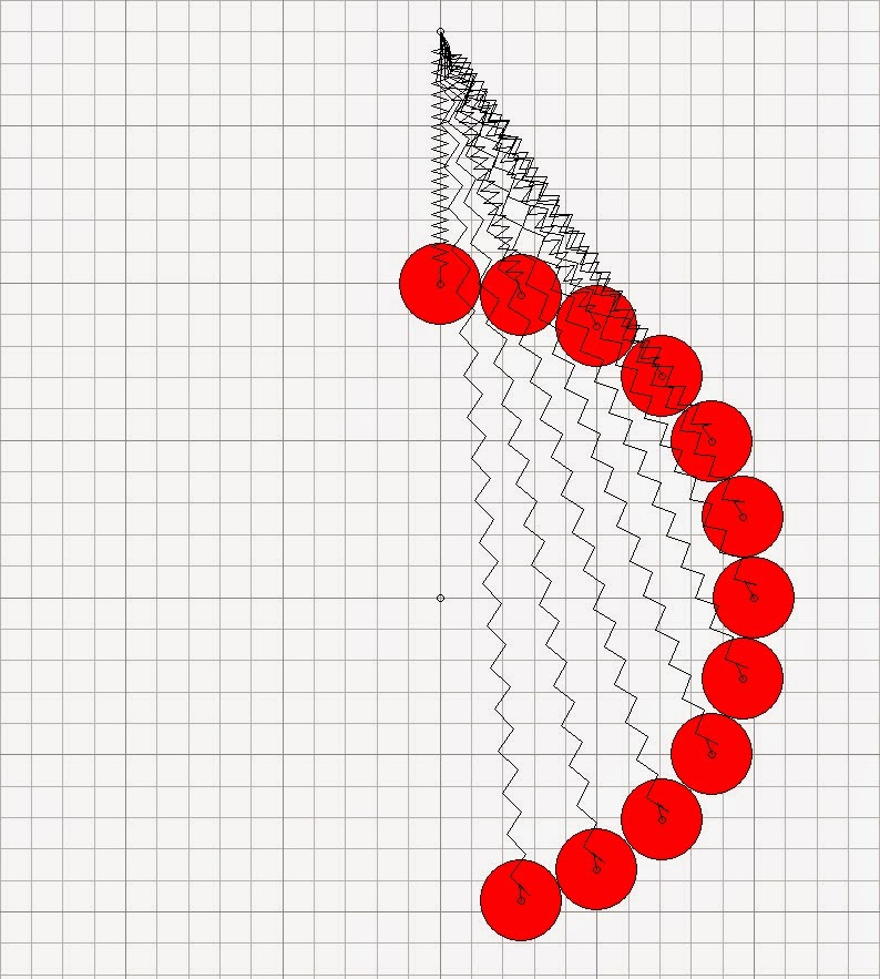

A stack of weights, all on the descending side


Description

Each 4kg weight in the stack is attached to, and can pivot around the central fixpoint. (In my earliest models I used arms between the weights and the fixpoint, which may look more realistic, but are unneccessary in the model. I haven't bothered with them here). The weights also have tension springs to the upper fixpoint. As each weight falls, its spring is extended, storing energy. The lowest weight goes "over-center" and is then pulled up by its spring on the ascending side.

All weights except the bottom one should be pinned together, because even though the top weight is in unstable equilibrium, it doesn't move from rest in the model, if it is left isolated from the other weights.

Results

Does the lowest weight get back to top center again? Fairly obviously, no. Even though a model like this could have only one weight at a time on its ascending side, as opposed to any number of weights on its descending side, energy is always just conserved overall between potential energy and kinetic energy of the weights, and stored energy in the springs. What is more, and what is perhaps not always appreciated, is that in any device like this, energy is always conserved overall at every instant over the entire operating cycle.

Variations

I investigated a few variations of this model, e.g. with the upper ends of the springs no longer attached to a fixpoint, but attached instead to small-diameter rollers which themselves formed a vertical stack, being pulled downwards at an appropriate rate, and hence delivering energy into the system. But none of these variations gave any net energy output.

Monday, 14 April 2014

Objections to Mechanical Perpetual Motion


The First Law of Thermodynamics — a "mantra"?

The first objection to perpetual motion raised by an orthodox scientist will probably be "It can't work because it will violate the First Law of Thermodynamics." Let's cast a critical eye over this law.

First, a point almost too minor to mention: The First Law is not the first law of thermodynamics. That honour belongs to the Zeroth Law of Thermodynamics.

The First Law of Thermodynamics can be written as the expression

             Q = (Uf - Ui) + W

or sometimes in differential form

            dQ = dU + dW

where Q is the heat absorbed in a thermodynamic system
            Uf is the internal energy function of the system in its final state
            Ui is the internal energy function of the system in its initial state
            W is the work done by the system

So, it is obvious both from its title and from its expression, that the First Law of Thermodynamics is applicable to heat engines, i.e. to devices whose operating principles depend on heat being absorbed or delivered. The same is true of the Second Law of Thermodynamics, which a perpetual motion machine is also sometimes said to violate.

If anyone wishes to extrapolate the First Law and/or the Second Law to apply to devices that do not depend on heat transfer, surely they must explain, in detail, why we should take any notice of them? Otherwise, for such devices, these laws risk being regarded as just impressively-titled but meaningless mantras.


The weight-driven perpetual motion machine.


Temporarily assuming the rôle of an orthodox scientist, here I'll set out as well as I can, what I understand to be the main objections raised by modern science to a weight-driven perpetual motion machine.

I'm aware that some critics might be unhappy with the way I've worded these objections. So I'm happy to be corrected — if there are any objections to my wording of these objections!

As far as I can see, there are only three basic possibilities for the operating principle of a weight-driven perpetual motion machine. These could act either alone, or in combination.

Gravity

i) Gravitational mass is what matters, i.e. the machine works by the action of the Earth's gravity on its weights.


Objection:— The Earth's gravitational field g is conservative, so if we obtain energy of mgh by allowing a mass m to fall through a height h within that field, we must always expend no less than mgh to return it to its starting point (or to any other point at the same height). We must return the mass to its starting point in order for the machine to continue to operate. Whatever path the mass follows within the field, while it is falling or rising, makes no difference to the energy obtained or expended over the total fall or rise.

Inertial propulsion

ii) Inertial mass is what matters, e.g. the machine is a wheel containing a number of "inertial propulsion" devices arrayed around its rim to give a "Catherine wheel" effect.

Objection:— An inertial propulsion device cannot work. If it did, it would have to disobey Newton's third law of motion, one of the most fundamental and never-broken laws in physics.

Energy from Earth

iii) The machine extracts energy from the rotating Earth.

Objection (Quoting directly from a Nobel Laureate in physics):—

"If your process is to extract energy from the Earth's rotation then the Earth will slow down to conserve energy, and conservation of angular momentum would appear to forbid this". The law of conservation of angular momentum is another of the most fundamental and never-broken laws in physics.

Frankly, unless I'm overlooking some subtlety, this last objection seems to be a fairly weak one. If we can postulate a device that transfers energy from the Earth to itself, then why can it not also transfer angular momentum from the Earth to itself, in such a way that both energy and angular momentum remain conserved overall? I may have more to say about this later, but I don't want to get too far ahead of what is intended to be a more or less chronological blog.


Sunday, 13 April 2014

Computer Modelling in 2D - Part II

 
Manuals

Back in 2002 I ordered the full set of silux manuals as shown below:—


The silux business model was to provide the program itself as a free download, together with some free documentation, and then to sell these manuals to serious users.

The User Guide has about 460 pages, the Script Language Guide about 160 pages, and the Upgrade Manuals for Versions 1.2 and 2.0. have 40 and 31 pages respectively. The Tutorial/Cookbook/Samples is just a copy of the three free pdf documents.

The whole lot cost me 180 Euros, with free delivery.

I now consider myself a proficient silux user, and these manuals were, and still are, very useful. Unfortunately, as far as I know, they are no longer available from silux ag in Switzerland. However, the most important documents of all, particularly for beginners, are the three pdf documents which are still available from the silux website. These are certainly enough to get started on some useful modelling.

Tips

Since I have learned most of these things "the hard way," the following list of workarounds etc for silux's various bugs and quirks may be of some interest to other users:—

Exploding models (rare but can happen): Try making all links and/or interaction constants harder. Or, make a small object of mass 1 gram or less (which I call a "timer"); place it where it won't hit anything else; make it a non-member for simulation (uncheck that in the edit object box) but still interacting. The aim is to reduce the time between iteration cycles, dt.

Also, if high-energy impacts take place over very short times, e.g. with "custom" interaction constants harder than "very hard", or with extremely strong compression springs, a timer will probably be needed to improve accuracy, (to any desired level, at the cost of longer simulation time — but the timer only needs to be set at low mass over the impact duration).

Also, avoid models with long flat surfaces bearing against each other, e.g. a long flat-sided piston in a cylinder. Keep bearing surfaces short.

Hollow objects: Use negative masses for cutouts. See how silux do this in their clockwork model. Otherwise rotational inertia will be wrong.

Micromovements: If the model is not starting from rest, assign correct velocity and rotational speed values for all objects, no matter how light, at the start of a simulation. Otherwise graphs may be "noisy". Occasionally, e.g. if accurate forces in links must be graphed, it may be necessary to calculate initial forces on some objects (e.g. centrifugal forces), and pre-load the model with these. So: calculate and assign them, (making sure that objects can only move in allowable directions for the pre-loading); run the model, periodically stopping all motion until it has settled down; then remove the forces. When restarted and running as intended, graphs should then be very smooth and accurate.

Yes, it may be tedious to do all this assigning of velocities, pre-loading etc, but on the other hand it can give a lot more confidence that the model really is set up and working correctly, and will give correct results.

Significant figures: Silux often displays only three significant figures e.g. for spring maximum force Fn. But for accurate work you can enter values to many more significant figures and silux will act on these, and will record and display to six significant figures in data associated with graphs.

Compression springs: These can display incorrect forces in graphs, but will still act correctly in models.

Dampers: Always graph damper force vs time to be sure a damper is working correctly. Either it will be, or if not, it will display zero force, and it will have to be re-made.

Gears: If gears are created using the silux method "Create Gear" and "Create Link Gearing" etc, this is the one case where the simulation results will probably be incorrect. Energy does not seem to transfer correctly across the gear link. If that's important, it would be best to model the gears as normal objects, complete with their teeth (only use simple arcs and/or straight lines — silux can't handle involutes!) The simulation will take longer, but it will be correct.

Saving: Never save a model with a graph minimised. You won't be able to recover the graph, and you may get an unhandled exception error which will crash the program.

Black screen: If the model window goes mostly black, e.g. after running a macro that has STOP SIMULATION, just click on that window.

Closing: To close (exit) the program easily, don't close the model window first.

Torque vs angle analysis

As a final tip, when analysing a proposed perpetual motion wheel, especially one that has multiple mechanisms of the same kind, I often find it useful to:—

    1.  Model the wheel with just a single mechanism installed. Also add a single counterbalancing weight (if continuous balance of the mechanism's weight is important).
    2.  Activate a macro to force the wheel to rotate at a constant rotational speed.
    3.  Record wheel torque vs wheel angle over a full revolution (in silux, set up a graph of these quantities, and use the Record button).
    4.  Transfer the recorded data into a drawing program, draw the graph of torque vs angle, and integrate it (i.e. find the area under the graph) to see if there is any net energy output.

This method can give a detailed and accurate result in less time than it would take to build a complex model with multiple mechanisms. Yes, such models can be built in silux using Script macros, but I still prefer the method described. One reason is that it's easy to see the magnitude of the torque, and exactly where it goes positive, and where it goes negative, etc, allowing the model's behaviour to be better understood.

Monday, 7 April 2014

Computer Modelling in 2D - Part I

Computer Models

After having built several (unsuccessful) real physical models and part-models to test various ideas, I decided to change to computer modelling of mechanical systems. Generally speaking, such modelling can be done far more quickly and accurately than building physical models. It's also possible to artificially increase/decrease/eliminate friction, or gravity, etc; to add external forces and torques; even to write code that will force objects to behave in any desired way, etc.

Of course, any user who wants to build a realistic model must ensure that, in its final form, it is "true", i.e. it is consistent with how Nature actually behaves!


A silux macro that forces an object (o1) to behave as a point on the Earth's surface at the equator would behave, as seen in a non-rotating frame attached to the center of the Earth. (Note the centimetre-gram-microsecond system of units).

silux

Most of the mechanical system modelling that I do only needs to be in 2D. In 2D models, all motion takes place in a single plane, or series of parallel planes.

My favorite 2D computer modelling program is, and always has been, silux. (Some firms like to drop capital letters of their names down to lower-case ones; a procedure rigorously followed by silux, so I go along with it).

The main developer of silux was Swiss physicist Fritz Leibundgut, (who now has a website at http://www.realphysics.ch/). silux is a finite differences program, rather than the much more common finite elements programs, which gives it some important advantages; see http://www.silux.com/faq2.cfm for more. For example, the user has the ability to stop a running program whenever desired, make any changes desired to the model, and then restart it — which cannot be done with anywhere near the same freedom in a finite elements program. (Bottom line: silux is more versatile; also I would trust it to give correct results, more than I would trust any finite elements program).


A problem — and a solution

Although the silux website is still up, at http://www.silux.com/, it is now obsolescent. It is still possible to download three free pdf documents, together with the program itself, from http://www.silux.com/software_download.cfm. However, the last time I downloaded and unzipped the silux program from this site, there was a problem. Unless silux have fixed it by now, I think this problem will occur for all users of 64-bit computers (i.e. almost everyone these days): double-clicking on "silux-2D setup" will bring up the error message:—


At first, I couldn't find any way around this problem. (I have only a generally fairly limited, self-taught knowledge of computers). I even thought for a while that silux wouldn't run at all on a 64-bit computer. But I was wrong — I have found that it is possible to run silux perfectly well on a 64-bit computer running Windows 7. Here is what I did:—

I downloaded, unzipped and installed silux on a 32-bit computer (I had already done that several years before). I copied the program itself (silux-2D.exe, a 4.16MB application file) to transferable media, (a flash drive) and copied it from that into my 64-bit computer. That's all!

To find out if a computer is 32-bit or 64-bit, click "Start", right-click "Computer", click "Properties" and look under "System > System Type".

See http://www.realphysics.ch/E_silux.htm for some more comment on silux by its developer.

I was thinking about uploading the silux-2D.exe program to this blog, so that those who no longer have access to a 32-bit computer could download it. I couldn't imagine any objection from silux, since the program has always been free. But apparently Blogger forbids uploading of any .exe file (to reduce malware risk).

Thursday, 3 April 2014

An Early Attempt at a Mechanical Perpetual Motion


Here are the only two full photos I now have of an early attempt at a mechanical perpetual motion machine. It isn't entirely naïve: the operating principle was intended to ensure:—

i) that the weights would always dwell longer on the wheel's descending side, while still exerting an average of their normal moment on that side (compared with a normally-supported weight in the same position); and

ii) that each weight would turn the wheel through a greater angle while it was falling on the descending side, compared with a smaller angle when rising.

Construction


There are two axes of rotation, separated horizontally, but kept rotating in synchronism by the gear train. The left axle carries a hub to which the bases of the springs are attached, as in this photo. The right axis of rotation is the center of the system of linkages whose purpose is to keep the "structure" of the weights as shown, i.e. always with an excess of weights on the descending side.


Ideally, the "structure" of the weights would be as shown above, every 1/8 of a revolution.
Although the springs were made as strong compression springs, here they are acting as
cantilever springs. Their length does not change; they only bend forward or backward with respect to the hub. During each wheel revolution, each composite-mass and its associated spring-pair make exactly one cycle of forward then backward movement.

Testing

During testing, I did achieve one aim, of spinning the wheel at a high enough rotational speed for this forward and backward movement to coincide with the natural resonant frequency of the masses and springs. As I recall, that speed was quite high. I didn't expect the resonance to be very "sharp" or of "high-Q", and it wasn't. (For one thing, gravity tries to retard the mass-spring oscillations by opposing the springs' restoring force above the horizontal centerline, and it has the opposite effect below the centerline. So the masses are always being "driven" or "driving" to some extent, even at resonance).

Although this machine didn't deliver any net energy, it generally behaved mechanically better than I had thought it might, running very smoothly at resonance. (Just as well, as a sudden stop from high speed of eight 12kg weights could have caused a fair bit of damage). Also, using a stroboscope, the structure of the weights could be seen to approximate the ideal shown in the drawing, better than the "at-rest" photos would suggest.

Several years after building this physical model, I built some silux models of devices that always had far more weight on their descending side than on their ascending side. I'll discuss two of them in future posts.