Saturday 28 May 2016

The Galtech Carousel Motor/Generator

Primary references:—

Lightworks video "Free Energy — The Race to Zero Point"

US Pat 5625241

Also see http://blog.go-here.nl/4831


More electrical power claimed to be delivered than used


Here are two screenshots from the 2008 Lightworks video "Free Energy — The Race to Zero Point."  The first one shows an Energy Research Corporation advertisement. Its introduction states "In controlled laboratory tests, the ERC's new motor/generator technology delivers more electrical power than it uses. This incredible breakthrough could one day make your electric bill a thing of the past."

The second screenshot shows a closeup of this "carousel" motor/generator, invented by Russell R. Chapman, Harold E. Ewing and principal inventor David R. Porter of Galtech Semiconductor Materials Corporation. It was claimed to be particularly suitable for high speed/high frequency operation.

Energy Research Corporation was a wholly owned subsidiary of Galtech Semiconductor Materials Corporation, which was itself renamed Real Data Inc. in 2013.


This full video has been posted at https://www.youtube.com/watch?v=PfEbCBcddQw. The section concerning David Porter and the carousel motor/generator starts at 59:54.

A strange claim

I don't propose to comment on the Galtech carousel motor/generator in detail. I'll just note one very strange claim made by David Porter, that it takes energy from an ongoing loss of strength of the permanent magnets incorporated in it.

Porter is not the only inventor to make such a claim. I'll examine it more closely in the post after next.

Saturday 14 May 2016

Repulsion Motor UAER — Drum vs Disc Part II


Disc design modelling, without repelling stator magnets


Fig 3a  Disc-design model

Figure 3a shows one of my early models of a toroidal electromagnet plus permanent magnet, as would be used in a disc-design UAER motor. The pole pieces on the electromagnet core (grey) are each 96 × 60 × 6, with 0.5mm airgaps to the 96 × 60 × 16 NdFeB35 magnet (blue). So the magnet has the same surface dimensions and total thickness as the magnet pair used before in the drum design. The electromagnet coil (transparent red) has a 4927.5 mm² current injection plane (solid red) which in this model delivers the same constant square-wave excitation pulse of 16400 amp-turns while the magnet is being vertically displaced from 0 to 96mm, as before.

The magnet is first attracted in to the unenergized core, until there is zero vertical displacement, as shown. The electromagnet is then energized as noted above, to repel the magnet out from the core.

Once again, only forces in the vertical Z-direction are relevant to the analysis.

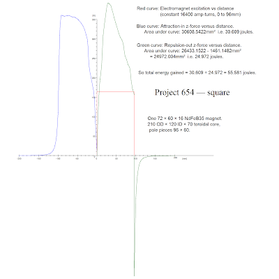
Fig 3b   Modelling results, square-wave excitation

Results

Figure 3b shows graphed results from this modelling.

The total energy gained is 55.581 joules, without any added stator magnets. This is a worthwhile improvement over the drum design, with or without stator magnets added to the latter. Admittedly the toroidal electromagnet core has a somewhat larger cross-section than the core of the drum design electromagnet, but the total volume of steel is much the same between the two options. They also have exactly the same total permanent magnet volumes, and excitations.

So, at least from the work done so far, it seems that the disc design of the UAER motor is preferable to the drum design.

Further modelling

Fig 4   Modelling results, half-sinewave excitation

I have done quite a lot more modelling of versions of this design. Figure 4 shows graphed results from the same model as shown in Figure 3a except for a reduced-length permanent magnet, but with the excitation now a half-sinewave, with details as noted on the graph (red curve). This modelling was done for comparison with some real-world experiments, which I may discuss in future posts.


Fig 5   An experimental toroidal electromagnet I built in 2009