Thursday, 28 August 2014

Coriolis Force and Inertial Propulsion Part II

The centrifugal gun and Newton's third law

Previously I have pointed out that the only force exerted on the mass-projectile in a centrifugal gun, Fc, and the reaction force exerted on its rotor, Fr, are always both perpendicular to the mass's direction of motion. However, any force bringing the mass to rest must of course be exerted along its direction of motion. This raises the question:— if the rotor is otherwise unconstrained while it rotates, is Newton's third law still obeyed overall between the mass and the rotor?

Back in the early 1980s, I decided to look into this in some detail.


Coriolis force vectors exerted on a rotor expelling a mass

The image above shows the Coriolis force reaction vectors (blue) being exerted on an anti-clockwise turning rotor, when a mass enters it, and is accelerated through a radial tube in the rotor. The first question of interest is: when added, do the Coriolis force vectors give a resultant that has a direction exactly opposite to that followed by the expelled mass? 

To put this another way: when the mass has been expelled, is it travelling in a direction exactly opposite to that of the rotor? Furthermore, is there an exact balance between i) the force through distance required to slow the mass down and reverse its direction for the next operating cycle, and ii) the force through distance required to bring the rotor to rest? Unless both of these conditions are met, an inertial propulsion machine must be possible. (Recall that Newton's third law requires an equal and opposite reaction force).

Was I first?

Before attempting any answers, I should mention that although I once thought I was first to see this possibility, I don't think so now.
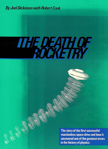

The Death of Rocketry
In 2000 I obtained the book The Death of Rocketry (1980) from author/inventor Robert Cook (see http://www.forceborne.com). This book is mainly concerned with Cook's two inertial propulsion inventions, see US Patents 3,683,707 and 4,238,968.

However, I found these inventions less interesting than another idea discussed and illustrated in the book, as shown, which is essentially the same as mine, and was probably thought of earlier:—
The Death of Rocketry, Fig. 6-14, p85

The comment on this idea (by co-author Joel Dickinson) ends:—

"The principle looked sound, but to construct a model would be nightmarish. To Cook, destroying all this energy by collision seemed a crime, so we abandoned these ideas."

I am not at all convinced that the kinetic energy imparted to the masses must necessarily be "destroyed". I think it would only require a bit of engineering (not especially difficult) to recover this energy.

Silux models, and further work

When I had become proficient with silux, I made a few models of this "inertial propulsion by Coriolis force" idea. As far as the questions I posed above are concerned, I can only say at present:—

- None of my models have shown any deviation from an exact 180º angle between the direction travelled by the mass and that travelled by the rotor, after the mass has been expelled from the rotor. So my modelling so far does not indicate any possibility of inertial propulsion.

- However, I have done nothing more than a few spot-checks, only on rotors with radial tubes, turning at constant speed. So I have not checked any rotors with the following adaptations:—

- Curved tubes or varying speeds (including various methods of imparting and varying rotor speed).

- Obtaining a high initial impulse-force when the mass is first picked up by the rotor, as suggested in Cook's Fig. 6-14 above.

- Making the mass as a gear, whose teeth mesh with a rack in the rotor's tube, and also possibly varying the rotational inertia of the gear-mass during the operating cycle.

All of these things are worth checking, and are on my priority-list, but other things have a way of intervening!

Saturday, 23 August 2014

Coriolis Force and Inertial Propulsion Part I

The Centrifugal Gun concept — the McCarty centrifugal gun

The McCarty centrifugal gun
I found this image at http://strangengines.wordpress.com/2008/08/04/the-mccarty-centrifugal-gun/. It shows the centrifugal gun patented by Robert McCarty (US Patent 1049, issued 31 December 1838). 


The Popular Mechanics centrifugal gun


The Popular Mechanics centrifugal gun
I also found the above article from Popular Mechanics magazine, which I can remember first reading many years ago. It was my first introduction to the concept of the centrifugal gun.

As this article says, "This may set you thinking of the potential of a centrifugal gun whirled by a gas turbine at, say, 20,000 r.p.m. With an effective swing radius of about 6in., you'd get a muzzle velocity of over 5000 f.p.s.— better than a high-powered rifle!"

There have been some dramatic claims made for recent developments of the centrifugal gun (notably the "Dread" by Trinamic Technologies, see https://www.youtube.com/watch?v=-teEbB9vlEU). But as far as I'm aware, such claims have yet to be proven by testing of physical prototypes. (It's always possible that tests have been done, but are currently classified).

Centrifugal gun — operating principle


In the above schematic drawing, the spherical projectile-mass enters the rotor near its center. It then experiences a Coriolis force Fc exerted on it from the side of the radial hole through the spinning rotor. This causes the mass to accelerate outwards along the radial hole and to leave the rotor at high velocity.

A possibility of inertial propulsion? 

By Newton's third law, Fr, an equal and opposite force to Fc, is exerted on the rotor. Note that, at every instant during the mass's travel through the rotor, Fc and Fr are perpendicular to its direction of motion. This raises a (slight) possibility of inertial propulsion, which I'll discuss next time.

Monday, 18 August 2014

Launching Spacecraft with Centrifugal Force

Could centrifugal force ever be used to achieve the difficult, high-energy objective of launching a spacecraft? This idea was indeed proposed, more than a century ago.


Fig. 1  A spacecraft launching system proposed by French
engineers in the early 20th century
My initial reference for most of what follows is The Dream Machines, a Pictorial History of the Spaceship in Art, Science and Literature, by Ron Miller, Krieger Publishing Company, 1993.

The Mas and Drouet catapult

In "La Catapulte tournant de Mas et Drouet", L'Avion 1913, French engineers Andre Mas and M. Drouet proposed attaching a projectile to the rim of a spinning wheel (shown at
http://www.bdfi.info/img_forum/petitinventeurgraffigny1.jpg). When the projectile reached a high enough speed, it would be detached and launched vertically, into space.

A very similar idea was proposed two years later by H. de Graffigny.


Fig. 2  The Fezandié launching system, illustrated by Frank R. Paul

The Fezandié catapult

In his story "A Car for the Moon", Science and Invention magazine, September 1923, author Clement Fezandié again proposed a similar idea. In this case the 30 ft diameter wheel is spun by the electric motor beneath it. The radial distance of the two-passenger craft is gradually increased by feeding out the chain between it and the wheel's axis, as shown. At maximum radius and speed, the craft is released.

Obviously the Fezandié system, as drawn, requires some method of keeping the craft correctly oriented. This would include, among other things, swivel links in its chain. But assuming such details were sorted out, what velocity must the projectile/craft reach, and what acceleration must it withstand in reaching it?

Escape velocity

The velocity required to launch a projectile so that it escapes entirely from the Earth's gravitational influence is about 11.2 km/sec, ignoring the effect of the Earth's atmosphere. However, in practice we cannot ignore the atmosphere, which would cause most objects travelling at this speed (nearly Mach 34) to break apart and/or burn up.

Acceleration and "g-forces"

In the system shown in Fig. 1, with the wheel turning at 40 turns/second = 251.33 radians/sec, the projectile at 50 meters radius will experience a centripetal acceleration of ω²r = 3,158,338 m/s² (nearly 322,061g). So it and the similar Fezandié system, with its chain at any reasonable length, would both exert higher g-forces than any structural material, much less a human being, could withstand.

So, it is not practical to launch a spacecraft by the centrifugal-force method discussed, because of the serious problems arising from the very large velocity and centripetal acceleration required.

A force perpendicular to the radius

I'll end this post by pointing out that the force accelerating the circumferential speed of the projectile must be exerted perpendicular to the radial line from it to the wheel's center. This leads into the concept of inertial propulsion by Coriolis force, to be discussed next time.

Wednesday, 13 August 2014

Computer Modelling in 3D

A Russian model of an American tank.
Universal Mechanism's model of an Abrams m1a1 tank, for detailed analysis
of track and vehicle behaviour over uneven terrain.

A good 3D modelling program

After some months of looking around for a good 3D modelling program, I decided to go with Universal Mechanism (UM). This program is under active and ongoing development by Prof. Dmitry Pogorelov and his team at Bryansk State Technical University in Russia. The website for English-language visitors is http://www.universalmechanism.com/en.

There are many YouTube videos posted by UM of simulations using their program (just search for videos by uploader universalmechanism) but these are all very short — too short to really show what the program can do.

Although there are other 3D modelling programs which are no doubt very good, the main reason I chose UM was that, unlike most, it clearly does cater for private individual users. The price for UM Base (the full program) is a very reasonable $150 US for an individual user. Additional specialized modules can be purchased as desired. UM's pricing schedule is at  http://www.universalmechanism.com/en/pages/index.php?id=11

UM Base can be downloaded for a decently long free trial period (a total of two months, from memory).

There is also a "lite" version, UM Lite, which is always free for an individual user, but I found it was too limited for my purposes.


Universal Mechanism's model of a spinning top.
Here, UM chose to build the model up entirely from parametric equations, rather than from a drawing.

Learning curve

As with any other program, there is a learning curve, which can be a bit steep at first, but worth it. Still, I have a long way to go to become really proficient. I'll give just one tip at this stage:—

I find it easiest to start building the model as a 3D drawing in a CAD program, and import it into UM as a .3ds file. Saving it again as a UM CAD file converts it into the .ucf format UM requires. With this approach, provided the model is not too complex, it may be easiest firstly to create all objects at the origin (0,0,0), and then to use the coordinates of the joints connecting them to place the objects correctly in the model.

Friday, 8 August 2014

The Todeschini/Di Bella Device Part III

Maybe an inertial propulsion?

Early on in the paper On Propulsive Effects of a Rotating Mass, Prof. Di Bella discusses a development of his device which is essentially that shown below. I have also drawn the locus of one of its two out-of-balance masses, from the equations given in Di Bella's paper. 


The Todeschini device, very similar to Di Bella's second device
Mass locus of Di Bella's second device


As far as I know, this device was first invented by Professor Marco Todeschini in 1933, see http://www.circolotodeschini.com.

As can be seen, the relatively minor design change from a single mass to a pair of offset masses, causes these masses to move along loci that are very different from the original. Provided that the design proportions are correct, each mass now has what Di Bella calls a "checkpoint", i.e. a sharp discontinuity in its motion. At this point, which is the only such point in its operating cycle, he says "...the device behaves as if it were struck by an external force..."

Tests

Di Bella and his team subjected various versions of this developed device to extensive testing. These ranged from large versions that could move an automobile sideways, or propel a boat, to smaller versions that were investigated under extremely low friction conditions, e.g. mounted on dry ice sliding across a horizontal smooth slate surface, or on a balanced arm on a very low friction point-pivot, in a 98.4% vacuum.

In these tests, the device behaved just as well in the vacuum as it did in air, whereas a small motor-driven propeller that worked well in air on the same test rig failed to work at all in the vacuum. In the dry ice/slate tests, a running device that was pushed out against its desired direction of movement would slow down, stop and return backwards.

Discussion

In discussing his results, Di Bella wrestles with the obvious problem:—

"...It seems very difficult to give an explanation for this forward motion. On the one hand, we have definite proof that the device advances, even in the presence of an extremely small amount of friction; on the other, we have the theorem of the motion of the center of gravity, which excludes the possibility of the device advancing, unless there is a friction resistance."

Limits to Newton's laws?

Although the large versions of this device were no doubt interacting with their surroundings, it's hard to see how that could entirely explain the performance of the smaller, extremely low-friction versions. These at least raise the possibility that William O. Davis, a former Director of the US Air Force Office of Scientific Research, was right in suspecting that Newton's second law of motion might not deal properly with cases where higher derivatives of displacement than just velocity (dx/dt) or acceleration (d²x/dt²) are involved. Shock loads, as would occur at the "checkpoint", have many such higher derivatives.

(Reference: "The bigger they are, the harder they fall," Prof. Eric Laithwaite, Electrical Review, 14 February 1975, citing Davis, W.O. "The fourth Law of Motion," Analog Science Fact and Fiction, August 1962 (British Edition), pp. 96-107).

What I should have built

With hindsight, it's easy to see that, rather than the model discussed in my last blog post, with its "smooth" mass locus, I should have built a version of this device with the "checkpoint" in its locus. I may yet do that in future, but currently I have other things higher on my priority-list. 
3D drawing of Di Bella's second device

I did prepare this somewhat schematic 3D drawing, which would be easy enough to turn into a 3D computer model for dynamic analysis. But if it really does depend on non-Newtonian physics, then any model built with currently available modelling software would not be valid.

Sunday, 3 August 2014

The Todeschini/Di Bella Device Part II

Professor Laithwaite's article

My original introduction to the Di Bella device was Prof. Eric Laithwaite's article "1975—A space odyssey" in Electrical Review magazine, 28 March/4 April 1975. In this article he quotes an eyewitness, Christopher Hook, who attended the 7th Symposium of Naval Hydrodynamics, Rome, in August 1968. There he was given a hands-on demonstration of a Di Bella device. He says:—

"...When he [Di Bella] arrived with this model without props, paddles or jets I rather naturally showed scepticism, whereupon the Professor thrust his model into my arms. On being switched on the model frog marched me, in a mild manner, towards the door by the action of rotating masses inside..."

I thought this was interesting enough to investigate further.

Background

Prof. Laithwaite mentioned in his article that Di Bella was granted a patent, but he didn't identify it further. In those pre-internet days patent searches were more difficult (and expensive) than they are now, so I didn't try to find that patent. Also, my first attempt to obtain Di Bella's paper On Propulsive Effects of a Rotating Mass was unsuccessful. I did manage to obtain a poor-quality photocopy in 1999. If I had seen it earlier, I would have noticed the second, even more interesting device shown as Figure 4 in the patent (US Patent 3,404,854) and discussed in detail in the paper, which I'll deal with in my next blog post. I now think that this is probably the device referred to by Christopher Hook.

I did see that while in operation, it would be possible to have the out-of-balance mass (of the first Di Bella device) move sinusoidally across its axle, with amplitude that could be varied externally, if desired, in real time. Stripped to its basics, my device was schematically as shown:—
Schematic drawing of my modified Di Bella device

And here it is, as a real physical device:—

My modified version of a Di Bella device. It is similar to the original except
that the out-of-balance mass can, if desired, be made to move across its axle,
at the rate of one oscillation per revolution. Its locus is drawn below.


The moving components, apart from the frame. The out-of-balance mass has an internal
ball-spline bearing, so it can translate but not rotate with respect to its splined axle.
Its position is controlled by a cam follower in its central recess. The user sets the cam
follower's position. And, yes, the hardened splined axle has not just been ground down,
but also threaded at both ends. More "hard-core" work — literally!


Locus for my modified Di Bella device at maximum oscillation amplitude

Tests

When spun up to speed using an electric drill driving via the flexible cable shown, this device would vibrate and move fairly slowly across a surface such as an old wood-topped table. But with only a moderate amount of testing, it was obvious that, like Di Bella's original device, mine also had to rely on interaction with its surroundings, by friction, in order to move. This was always so, whether the out-of-balance mass was moving across its axle or not. So it could not be a true inertial propulsion.